DPM Barcode Scanners for Manufacturing Traceability: A Practical Selection Guide
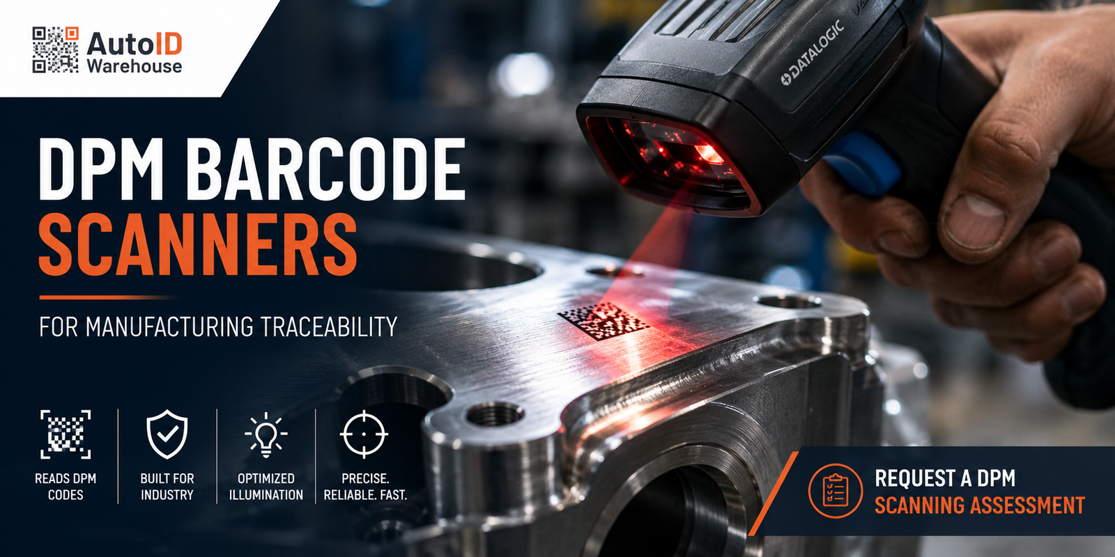
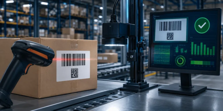
A barcode printed on a clean white label is an easy target. A tiny Data Matrix code laser-etched into a polished steel component moving through a production cell is an entirely different challenge.
That difference is where DPM barcode scanners become essential.
Direct Part Marking, or DPM, allows manufacturers to identify a component permanently by placing a machine-readable code directly onto the part. There is no label to peel off, no adhesive to fail and no printed tag that disappears during machining, cleaning, heat treatment or years of service.
The trade-off is simple: permanent marks are often much harder to read than printed barcodes.
Laser marking may create very little contrast. Dot peen codes depend on surface geometry rather than ink. A machined metal surface can behave like a mirror. A cylindrical component changes the angle of reflection across the code. Oil, scratches, machining patterns and oxidation make the problem even more interesting.
Choosing a direct part marking scanner therefore means looking beyond the decoder specification. Successful DPM reading depends on the relationship between the mark, the material, lighting, optics, working distance, part presentation and production process.
This guide explains how to evaluate all of them.
Content
What Is Direct Part Marking?
Direct Part Marking is the practice of applying identification directly to a component rather than attaching a separate label. The goal is usually to maintain a durable identity throughout production, assembly, service and potentially the full usable life of the part.
International technical guidance describes DPM as permanent marking applied directly onto a surface and covers techniques including laser marking, chemical etching and dot peen.
Why Manufacturers Use DPM Instead of Labels
Think of a normal barcode label as a passport carried by the product. DPM is closer to engraving the passport number into the product itself.
That permanence matters in automotive manufacturing, aerospace, electronics, metalworking, machinery, tools, medical-device manufacturing and other environments where identification must survive processes that would challenge conventional labels.
A DPM code can support:
production history, component genealogy, serialisation, work-in-progress tracking, quality control, assembly validation, maintenance records, warranty investigation and product authentication.
The code becomes the digital bridge between the physical component and the manufacturing information stored in ERP, MES, WMS, quality or maintenance systems.
Why DPM Codes Are Harder to Scan
A conventional barcode normally creates strong optical contrast: dark print against a light substrate. A DPM symbol often creates contrast indirectly.
The scanner may need to distinguish tiny differences in reflectivity, texture, depth or surface angle. Consequently, two marks that look almost identical to a person can produce dramatically different images for a barcode reader.
A metal barcode scanner may have to deal with specular reflection, machining lines, irregular backgrounds and code cells whose appearance changes when either the scanner or the component moves a few degrees.
This is why simply asking, “Does this scanner read Data Matrix?” is not enough.
Most industrial 2D imagers can decode Data Matrix in principle. The better question is:
Can this scanner create a consistently decodable image of our Data Matrix mark, on our component, under our production conditions?
That is a much more useful specification.
Data Matrix and DPM Manufacturing Traceability
Data Matrix is particularly well suited to applications where a significant amount of identification data must fit into a small physical area. In DPM applications, the symbol can be created directly on a component using marking technologies such as laser or dot peen. AIAG’s DPM guidance specifically addresses Data Matrix and QR codes used with processes including laser and dot peen marking.
For manufacturing traceability, the encoded information commonly acts as a key.
The barcode does not need to contain the component’s entire manufacturing history. It may contain a serial number, part identifier or other unique reference that connects the physical item to records elsewhere in the system.
A scan at each important process step can then establish a digital trail:
component received → machining → assembly → inspection → test → packaging → shipment.
The scanner is therefore not just a data-entry peripheral. At the right points in a production line, it becomes a checkpoint controlling whether the correct component moves to the correct process.
How the DPM Marking Method Changes Scanner Performance
Before choosing an industrial DPM scanner, understand how the mark is being created.
Laser, dot peen and chemical etching can all generate durable identification, but they present very different optical problems. International DPM guidance recognises these as established marking approaches, while scanner manufacturers design specialised illumination to handle the resulting surface characteristics.
Laser Marking
Laser marking is widely used because it can create small, precise marks and can be applied to many materials.
But “laser marked” does not describe one visual condition.
Depending on the material and laser process, the result may be dark against a light surface, light against a dark surface, subtly altered in colour or primarily visible because of a change in texture.
On polished metals, the surrounding material may produce much stronger reflections than the mark itself.
For a scanner, the challenge is often not resolution alone. It is creating enough usable contrast without allowing glare to overwhelm the symbol.
Dot Peen Marking
Dot peen uses a stylus to create small indentations in the material. It is especially common on metal components.
Instead of reading printed squares, the scanner is effectively interpreting a pattern of tiny three-dimensional features.
That makes illumination angle critical.
Low-angle lighting can cause the edges of each indentation to reflect differently from the surrounding flat surface, transforming physical depth into optical contrast. Cognex identifies dark-field illumination as particularly effective for dot-peen marks and surface topography.
Move the light, however, and the same dots can almost disappear.
Chemical Etching
Chemical or electrochemical processes can create durable marks while preserving a relatively flat component profile. Chemical etching is among the recognised DPM methods and is used in industrial applications where durable identification is required.
Here again, the exact appearance depends on the substrate and process.
The lesson is important: choose a scanner based on the actual mark, not just the name of the marking technology.
Two suppliers can both describe their process as laser marking while producing codes with substantially different optical properties.
The Surface Matters as Much as the Barcode
The barcode does not exist in isolation. Its surface is part of the imaging system.
A perfectly formed Data Matrix on the wrong combination of material, curvature and lighting can be more difficult to read than a less attractive mark on an optically cooperative surface.
Reflective Metal
Polished stainless steel, aluminium and machined components can create bright hotspots. The scanner sees the light source reflected directly into the imager, potentially washing out part of the code.
The solution is not necessarily “more light.”
Often the answer is better-controlled light.
Specialised DPM readers use multiple lighting techniques precisely because reflective, irregular and low-contrast marks need different illumination from ordinary printed barcodes. Zebra, for example, describes its DPM models as using advanced illumination to handle reflective, irregular and curved surfaces.
Curved and Cylindrical Parts
A code on a cylindrical shaft, tube or curved casting presents another problem: different parts of the symbol face the scanner at different angles.
One side may be well illuminated while the other reflects light away.
Curvature can also introduce geometric distortion. If the code occupies too much of a small-diameter cylinder, the perspective change across the symbol may become significant.
This is where field testing beats brochure comparison every time.
Rough, Cast and Machined Surfaces
Cast texture, grinding marks and machining patterns create their own edges and shadows. To the imaging system, this surface “noise” competes with the code.
A strong DPM reader must separate the intended Data Matrix structure from background features.
That may require a different light angle, wavelength, exposure, lens or physical orientation. Sometimes changing the position of the code by a few millimetres during the marking-process design is more valuable than buying a more expensive scanner later.
Illumination: The Key to Reliable DPM Reading
When DPM projects fail, the instinct is often to blame decoding software. Yet the decoder can only work with the image it receives.
Lighting is therefore one of the most important parts of DPM engineering.
Different illumination geometries reveal different surface characteristics, and specialist DPM systems commonly offer multiple lighting approaches. Verification standards for DPM also recognise multiple illumination angles rather than assuming a single lighting geometry fits every mark.
Dark-Field Illumination
Dark-field illumination introduces light at a shallow angle.
Imagine shining a torch almost parallel to a textured wall. Tiny imperfections suddenly produce visible highlights and shadows.
The same principle helps expose dot-peen indentations and other topographical marks. Cognex identifies low-angle dark-field illumination as particularly effective for dot-peen and laser-ablated surface features.
Bright-Field and Diffuse Illumination
Bright-field illumination approaches the part more directly and can work well when the mark and background return clearly different levels of light.
Diffuse illumination attacks a different problem: uncontrolled reflection.
Instead of creating one strong reflection from one direction, diffuse lighting spreads illumination across many angles. That can reduce hotspots on polished, curved or textured surfaces. Cognex specifically identifies diffuse dome lighting as useful for highly reflective and curved surfaces.
Polarization and Reflection Control
Polarisation can help suppress certain unwanted reflections and improve the visibility of surface detail.
But it should not be treated as a magic “metal mode.”
The useful configuration depends on the material, mark and optical geometry. A better engineering process is to evaluate polarisation together with lighting angle, camera position and exposure.
The principle is straightforward:
control the reflection instead of trying to overpower it.
That one idea explains why specialist DPM readers can outperform otherwise excellent general-purpose 2D barcode scanners.
Handheld vs Fixed-Mount DPM Barcode Scanners
Once the mark can be read reliably, the next decision is architectural: should an operator present a scanner to the part, or should the production process present the part to a fixed reader?
| Requirement | Handheld DPM scanner | Fixed-mount DPM scanner |
| Part orientation varies | Excellent fit | May require mechanical control or larger imaging strategy |
| Operator already handles component | Excellent fit | Possible, but integration may add little value |
| Automated high-speed line | Limited | Preferred |
| Consistent working distance | Operator dependent | Highly controllable |
| Controlled illumination | Integrated but mobile | Highly repeatable |
| Multiple scan locations | Easy | Usually requires multiple readers |
| PLC integration | Possible on some systems | Strong fit |
| Hands-free operation | Limited | Excellent |
| High throughput | Good for manual processes | Excellent for automation |
| Installation engineering | Low to moderate | Moderate to high |
There is no universally “better” architecture. There is only an architecture that better matches the process.
When a Handheld DPM Scanner Is the Better Choice
Handheld readers are ideal when variability is part of the job.
An operator may inspect different components, rotate a part to locate the code, scan assemblies at several positions or work at repair and rework stations where a fixed reader would be inconvenient.
A purpose-built handheld DPM scanner also gives the operator something a fixed system cannot: the ability to adjust position and angle instinctively.
If glare appears, the operator can tilt the reader. If the code is recessed, the operator can approach from a different direction.
Modern rugged DPM handhelds are specifically designed for this type of work. Zebra’s DS3600-DP family, for example, combines DPM decoding with specialised illumination for marks including dot peen and laser etch and is offered in corded and cordless configurations.
Handheld is usually worth considering for manual assembly, maintenance, quality inspection, receiving, rework, low-volume production or large components where the code position varies.
When a Fixed Industrial DPM Scanner Is the Better Choice
Fixed-mount readers become attractive when the process needs consistency, automation and throughput.
The camera position is controlled. Working distance is fixed. Lighting stays where engineering put it. A sensor or PLC can trigger image acquisition at the correct moment, and the result can be transferred directly into an automation system.
That repeatability is extremely valuable.
Products such as Datalogic’s Matrix 320 combine industrial imaging, integrated illumination and industrial connectivity for traceability applications, while AutoID Warehouse currently lists Matrix 320 configurations described for precise DPM reading.
Fixed-mount systems are especially appropriate when every component arrives in a predictable location, cycle time matters, scanning must occur without operator action or the barcode result determines what the PLC does next.
The cost comparison should therefore be bigger than “handheld price versus fixed-reader price.”
Ask what each architecture does to labour, takt time, error prevention and traceability completeness.
How to Specify a DPM Scanner Correctly
A good DPM specification starts with samples, not a catalogue.
Collect representative components from normal production. Include the beautiful marks, but also include the difficult ones: low contrast, minor contamination, different batches, different suppliers, edge-of-tolerance marking and realistic surface finishes.
Then document the application.
You should know the code type and approximate dimensions, smallest cell or module size, marking method, substrate, surface finish, curvature, required working distance, available mounting space, orientation variation and expected line speed.
Environmental conditions matter too. A reader on a clean electronics bench lives a very different life from one next to machining coolant, metal dust, vibration or repeated washdown.
For fixed systems, also define triggering, communications and the required response when a scan fails.
Does the PLC stop the line?
Does the system reject the component?
Can an operator perform a manual recovery scan?
What happens to the traceability record after a no-read?
Those workflow questions are part of scanner selection because a reader only creates value when its result is correctly integrated into the process.
Reading a DPM Code Is Not the Same as Verifying It
This distinction is easy to miss.
Reading asks: “Can this device decode the symbol?”
Verification asks: “How good is the symbol according to a defined quality methodology?”
A powerful scanner may decode a marginal mark that other equipment struggles to read. That does not automatically mean the marking process is healthy.
DPM verification can evaluate symbol quality using standards designed for direct marks, such as ISO/IEC 29158 methodology. Cognex’s DPM verifier documentation distinguishes this grading approach from ordinary Data Matrix verification and includes specialised illumination conditions.
For manufacturers, this creates an important process-control principle:
do not solve every poor mark by buying a more tolerant reader.
If mark quality is deteriorating, verification can help identify the marking process as the root cause before unreadable components move further into the supply chain.
A robust programme may therefore use production scanners for everyday identification and a verifier for process setup, auditing and quality investigation.
Building DPM into a Manufacturing Traceability System
Reliable decoding is only the first layer.
The real value appears when the scan becomes part of the manufacturing workflow.
Consider an engine component arriving at an assembly station. The DPM code identifies the individual part. The manufacturing system checks whether that serial number belongs to the correct production order. It can verify previous operations, associate measurements, record the assembly event and prevent a mismatched component from moving forward.
Now the barcode is doing much more than replacing keyboard input.
It is enforcing process logic.
For effective manufacturing traceability, decide what information each scan should create:
identity, timestamp, station, operator or machine, process result, parent-child relationship, batch, quality status or another event required by the application.
The physical scanner then needs the right interface to deliver that information where it belongs.
For automated lines, industrial Ethernet and PLC integration may matter as much as decoding performance. For manual stations, USB, Bluetooth or keyboard-style data transfer may be perfectly adequate.
Start with the business event and work backward to the hardware.
Common DPM Scanning Mistakes
One of the most expensive mistakes is selecting a reader from specifications alone.
“Reads Data Matrix” does not mean “reads every Data Matrix permanently marked on every metal surface.”
Another mistake is testing one perfect sample. Manufacturing varies. Tool wear changes dot-peen geometry. Laser settings drift. Surface finish changes between suppliers. Parts arrive with coolant or handling marks.
Testing should represent that reality.
A third mistake is treating lighting as an accessory rather than part of the system.
For DPM, illumination is effectively part of the decoding chain. Changing lighting geometry can transform a nearly invisible mark into a clear machine-readable image.
And finally, avoid assuming that a scanner upgrade can compensate indefinitely for a weak marking process.
The best result comes when marking and reading are designed together.
A Practical DPM Scanner Selection Workflow
A reliable selection project can be reduced to six stages.
First, define the traceability event. Decide exactly what must be scanned, where and why.
Second, characterise the actual mark. Identify marking technology, code dimensions, material, finish, curvature and expected variation.
Third, choose the process architecture. Determine whether the operator should move the scanner or the line should present the component to a fixed imaging system.
Fourth, test illumination and optics using representative production samples.
Fifth, validate interfaces and workflow behaviour, including no-read handling.
Sixth, run a realistic pilot using multiple components and normal process variation before standardising the hardware.
This approach may sound slower than selecting a scanner from a product page.
In practice, it is faster than debugging unreliable DPM reading after an automated production cell has already been commissioned.
DPM Scanner Options Available from AutoID Warehouse
AutoID Warehouse supplies barcode readers and industrial scanning systems from established manufacturers and currently lists more than 50,000 products and accessories across its wider AutoID portfolio.
For DPM projects, the useful starting point is not a single “best scanner” but the application itself.
For fixed installations, the current portfolio includes products such as the Datalogic Matrix 320, with configurations positioned for DPM and industrial traceability, and Omron MicroHAWK V430 configurations suited to industrial code reading and production integration.
The portfolio also includes Zebra FS10 configurations with DPM capability available as an option, giving integrators another compact fixed industrial architecture to evaluate.
For mobile applications, AutoID Warehouse lists dedicated DPM-capable hardware including the Code Corp CR3600 DPM, designed for 1D/2D and DPM capture in production and traceability workflows.
The important point is not the logo on the scanner.
It is whether the combination of scanner, lens, illumination, working distance, connectivity and mechanical arrangement has been validated against your actual marked components.
Request a DPM Scanning Assessment
If you are planning a new traceability project—or fighting intermittent no-reads on an existing line—start with the parts rather than the product catalogue.
Provide representative samples or application information covering the marking method, material, barcode size, working distance, line speed and preferred handheld or fixed-mount workflow.
The objective is straightforward: identify a DPM scanning configuration that works reliably under real manufacturing conditions, not only under ideal test conditions.
Conclusion
DPM barcode scanning is an imaging problem before it is a decoding problem.
Laser marking, dot peen and chemical etching create durable identification, but each interacts differently with metal, plastics, surface texture and light. Reflective and curved components make that relationship even more important.
That is why successful DPM projects combine the right Data Matrix DPM reader with suitable illumination, optics, positioning and process integration.
Use handheld scanners when operators need flexibility and access to variable part positions. Use fixed-mount industrial readers when repeatability, automation and high throughput dominate the application. And when code quality itself matters, remember that reading and verification are two different jobs.
Most importantly, test with real parts.
A datasheet can narrow the shortlist. Your component tells you which scanner actually belongs on the factory floor.
Frequently Asked Questions
What is a DPM barcode scanner?
A DPM barcode scanner is an imaging device designed to read barcodes marked directly onto a component, including low-contrast, etched, laser-marked and dot-peened codes that may be difficult for conventional barcode scanners.
What is the difference between DPM and a normal barcode?
A conventional barcode is usually printed on a label or package. A Direct Part Mark is created directly on the component itself, giving it a more permanent identity but often making the code optically harder to read.
Can DPM scanners read Data Matrix codes on metal?
Yes. Purpose-built DPM readers are designed for applications such as Data Matrix codes on metal. Successful reading still depends on mark quality, surface finish, curvature, module size, lighting and working distance.
Why are laser-marked Data Matrix codes sometimes difficult to scan?
Laser marks may create limited contrast, especially on shiny materials. Reflections from polished metal can also hide parts of the symbol. Specialised illumination and reflection control can significantly improve image quality.
What lighting works best for dot peen codes?
Low-angle or dark-field illumination is frequently effective because it highlights the geometry of the indentations. The correct setup should nevertheless be validated on actual production parts.
Should I choose a handheld or fixed-mount DPM scanner?
Choose handheld when operators need to scan parts at changing positions or orientations. Choose fixed-mount when the process is automated, component presentation is controlled and high repeatability or throughput is required.
Is reading a DPM code the same as barcode verification?
No. Reading determines whether data can be decoded. Verification grades characteristics of the physical symbol according to a defined quality methodology, helping manufacturers monitor the marking process itself.
Can one DPM scanner work with laser marking and dot peen?
Many specialised DPM readers are designed to handle several mark types, but performance should be tested on representative components. The required illumination for a laser-marked polished surface may differ significantly from the optimum setup for dot peen.
How should we test a DPM scanner before purchase?
Use multiple real production parts representing normal variation, including difficult marks, different surface finishes and realistic contamination. Test at the intended working distance, orientation and cycle time rather than using only a perfect sample.
Where can I get help selecting a DPM scanner?
AutoID Warehouse can evaluate handheld and fixed industrial scanning approaches for manufacturing applications. Request a DPM scanning assessment with details of your marked components and process requirements.